How can the LED display be connected more safely
Time:2018-10-12
Views:695
Full-color LED display fault has many are caused by improper installation, so the installation need in strict accordance with the steps to operate full-color LED display, especially the installation for the first time, so that we can reduce the error occurred, take a look at below DE embellish of self organizing, full-color LED display installation steps wiring method.
Check the power supply voltage
Locate the dc positive/negative connection switch power supply, connect the 220V power line to the switch power supply, (after making sure the connection is correct, connect to AC or NL terminal) and plug it in.It will be found that one of the power supply lights will be on, and then use the multimeter, dc file to measure the voltage between V+ and V-, make sure the voltage is between 4.8v and 5.1v, and there is a knob next to it, which can adjust the voltage with the cross screwdriver.To reduce screen heat and extend life, the voltage can be adjusted to between 4.5v and 4.8v in low-brightness situations.After confirming that there is no problem with the voltage, disconnect the power supply and continue to assemble other parts.
2. Connect power supply
Power off first, connect V+ to red line and V- to black line, respectively to control card and LED panel, and black line to GND of control card and power supply.The red line connects the control card to the +5V and the unit board to the VCC.1 power cord per unit plate.When done, check that the connection is correct.
3. Connect control and unit board
Use good alignment, connection.Pay attention to the direction.Please note that the unit board has 2 interfaces of 16PIN, 1 is input (in), 1 is output (out), and close to 74hc245/244 is input, connecting the control card to the input.The output is connected to the input to the next cell board.
4. Connect RJ45 network cable (data cable)
Connect one end of the completed network cable to the network port of the computer or the transmission network port, and the other end to the control card. Connect the other control CARDS one by one in the form of a-b and a-b.
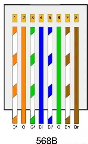
In order to achieve the best compatibility, T568B standard is commonly used in making straight through lines.The serial number of RJ45 crystal needle should be observed in the following way: put the front of the RJ45 plug (one side with copper needle) facing itself, have the copper needle facing upward and the end of the connecting cable facing downward. Number the 8 copper needles in order from left to right:
White background - orange, big orange, white - green, black - green, black - blue, white - green, white - brown

5. Check wiring
Check again if the connection is correct, the black line is connected to -v and GND.The red line connects +V and VCC +5V.
Red line to L, blue line to N, yellow and green line to earth
6. Test
Turn on 220V and open the downloaded software.Under normal circumstances, the power lamp is on, the control card is on, and the LED display screen is on.If not, please check the connection.Or check for faulty repairs.Set screen parameters and send subtitles.Refer to the software instructions.
分享


.jpg)


